
Machining a Damaged Flange Face: How Much Can You Remove Before You Need Weld Buildup?
Flange face damage (pitting, corrosion, scoring , or gouging) is a routine finding during plant turnarounds and in-service inspections. When you find it, and it is outside the allowable limits of acceptable defects per the code, you have two options: machine the face to a clean finish, or weld build up and then machine. The question that determines which path you take is simple: how much raised face material is left, and how much can you safely remove?
This article walks through the applicable ASME standards so you can make that call confidently, and explains how FlangeVision automates all of the measurement and math for you.
Step 1: Is the Damage Actually Out of Spec? Check B16.5 Table 3 First
Before you decide to machine anything, the first question is whether the damage even requires repair. ASME B16.5-2020 section 6.4.6 and Table 3 define permissible imperfections in flange facing finish. If a defect falls within these limits, no machining is required, the flange is within spec as-is.
The standard distinguishes between imperfections that are shallower than the bottom of the serrations versus those that are deeper. Deeper imperfections are held to a tighter radial limit, and also have a maximum depth limit:
Table 1. ASME B16.5 Table 3: Permissible Imperfections in Flange Facing Finish (Raised Face)
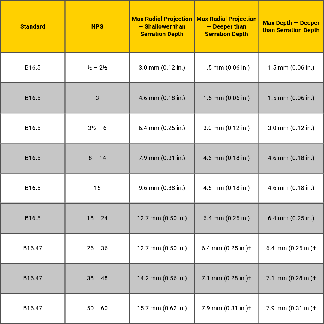
B16.5 source: ASME B16.5-2020, Table 3. B16.47 source: ASME B16.47-2020, Table 30. Dimensions in mm (in.).
† B16.47 Table 30 combines the max radial projection and max depth for deeper-than-serration imperfections into a single value, it does not split them into separate columns as B16.5 does. The same acceptance value applies to both criteria.
Adjacent imperfections must be separated by at least 4× the maximum radial projection. Imperfections less than half the depth of the serrations are not cause for rejection. Protrusions above the serrations are not permitted.
If the damage is within Table 3 limits: no machining required. Document and monitor. FlangeVision records imperfection measurements against Table 3 limits automatically, flagging whether the flange passes or requires repair, no manual lookup needed.
Step 2: Can You Machine Just Deep Enough for the Pit to Be Within Spec?
This is a question that comes up often in the field: rather than machining the entire face flat, can you machine only partway into the pit, just enough that the remaining pit depth falls within the B16.5 Table 3 limits?
What PCC-2 section 305-4.1 says is:
"If either the flange ring thickness or hub dimensions, or both, are sufficient, then the entire gasket surface may be machined to remove the area of degradation or imperfection and thus achieving the desired finish without weld metal buildup." — ASME PCC-2-2022, section 305-4.1
The language describes machining the entire gasket surface. The code does not explicitly describe partial pit machining as a repair method, but it does not prohibit it either. Below is a professional engineering perspective on why partial machining is a legitimate and defensible approach.
Engineering Opinion — Tim Gaida, P.Eng.
In my view, partial machining, stopping before the bottom of a pit, such that the residual pit geometry falls within the B16.5 Table 3 limits, is a defensible and practical repair approach, even though PCC-2 does not explicitly describe it.
Consider the logic: if after partial machining the raised face height is within spec and the remaining pit dimensions fall within Table 3, then a fresh inspection of that flange would pass it for service. The flange is, by definition, code-compliant. The fact that you arrived at that condition by machining rather than finding it that way at initial inspection is irrelevant to the outcome.
It may feel counterintuitive to stop machining while a pit still visibly remains. But time and cost on a plant shutdown are real constraints, and every additional pass of the facing tool removes material you cannot put back. Understanding the intent of the code helps here: Table 3 permits pits to a certain depth and radial extent because gaskets, particularly soft gaskets, have sufficient thickness and compressibility to bridge small imperfections. The gasket will compress into the pit, develop high local stress around the pit edges, and still achieve a seal. That sealing performance is the ultimate goal, and the Table 3 limits are built to it.
The key requirements for partial machining to be defensible are: (1) the finished raised face height must remain at or above the PCC-2 section 305-3.1 minimum of 0.8 mm, (2) the residual pit depth and radial projection must fall within the Table 3 limits for the flange NPS, and (3) the machined surface must achieve the required finish per B16.5 section 6.4.5. If all three are met, the resulting condition is one that the code would accept on initial inspection, and that is a sound engineering basis for accepting it after repair.
This is my professional opinion as a P.Eng. It is not a code requirement, and engineers of record should apply their own judgment to the specific conditions of each repair.
Step 3: How Much Can You Machine Off? The PCC-2 Floor
Once you've determined machining is required, ASME PCC-2-2022 section 305-3.1 sets the hard lower limit on how far you can go:
Under-thickness of a raised face due to refinishing shall be acceptable, provided the minimum finished height of the raised face is 0.8 mm (0.031 in.). — ASME PCC-2-2022, section 305-3.1
This 0.8 mm minimum applies regardless of pressure class or nominal raised face height. Below it, weld metal buildup is required before re-machining. PCC-2 section 305-3.2 also requires a formal thickness evaluation if machining removes material from the flange body beyond just the raised face.
Table 2 — Raised Face Machining Limits by Standard and Pressure Class
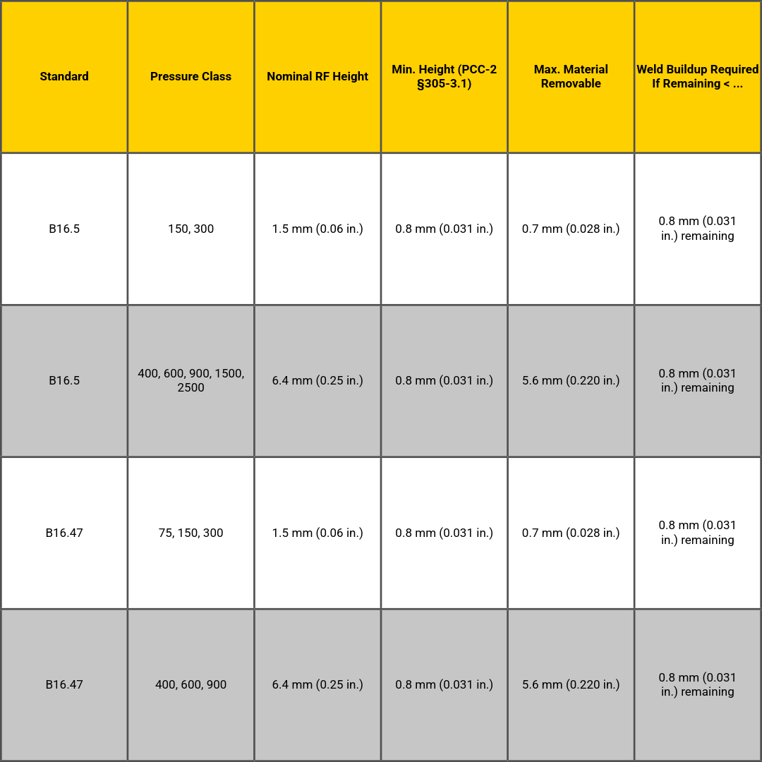
Nominal heights per ASME B16.5-2020 section 6.4.1 and ASME B16.47-2020 section 6.1.1. Minimum height per ASME PCC-2-2022 section 305-3.1.
Max. material removable = Nominal height minus PCC-2 minimum (0.8 mm), assuming a face at nominal. Always measure actual remaining height, a previously repaired or worn face may already be below nominal.
Weld buildup trigger: If machining to a clean surface would leave less than 0.8 mm (0.031 in.) of raised face remaining, weld metal buildup per PCC-2 section 305-4.2 is required before machining. FlangeVision calculates this in real time from your scan data.
How FlangeVision Automates This Entire Workflow
Every step in the decision above involves measurement and math that is time-consuming and error-prone when done manually. FlangeVision automates the complete workflow from scan to repair decision:
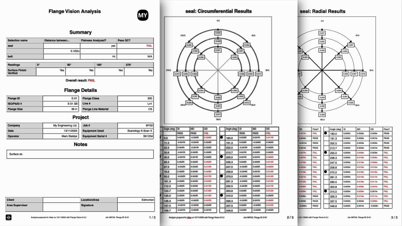
Measures the current raised face height directly from the scan — no depth micrometer required.
Maps pit depth and radial extent across the entire face and automatically checks each imperfection against B16.5 Table 3 (or B16.47 Table 30) limits for the flange's NPS.
Calculates remaining raised face height after machining to the deepest out-of-spec imperfection, and flags immediately if that falls below the 0.8 mm PCC-2 floor.
Outputs a repair recommendation: accept as-is, machine only, or weld buildup required — with the specific depths and code references included in the report.
What used to require a micrometer, a Table 3 lookup, a subtraction, and an experienced judgment call is now a single scan. FlangeVision gives you the answer, and the code citation to back it up.
Reference: Fabrication Tolerances on Raised Face Height
For completeness, the table below shows what the fabrication standards specify for raised face height tolerances on new flanges. This is the realistic starting point before any in-service wear, and is relevant when assessing a flange received from a manufacturer.
Table 3 — Fabrication Tolerances on Raised Face Height
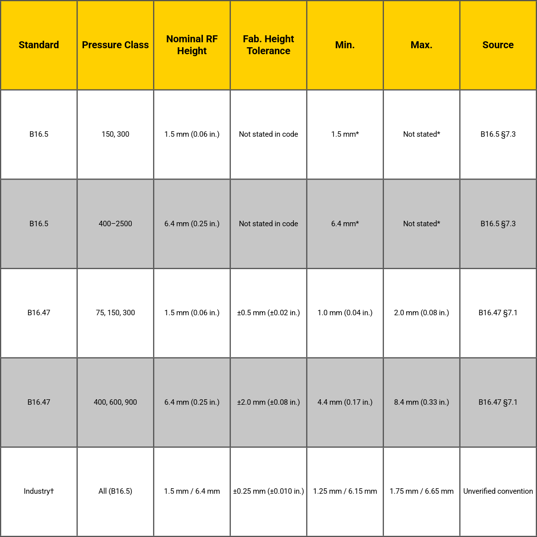
* ASME B16.5-2020 section 7.3 gives tolerances on the outer diameter of the raised face only, not on the height. The nominal height is effectively the minimum at fabrication due to the +/−0.0 mm negative tolerance on overall flange body thickness (section 7.4).
† The ±0.010 in. (±0.25 mm) value is widely cited in industry references as a practical shop tolerance for raised face height under B16.5. It does not appear in ASME B16.5-2020 and its original code source has not been verified. Included here as a common reference point only.
References
ASME B16.5-2020, Pipe Flanges and Flanged Fittings — section 6.4.1 (nominal RF heights), section 6.4.6 and Table 3 (permissible imperfections), section 7.3 (facing tolerances), section 7.4 (flange thickness tolerances).
ASME B16.47-2020, Large Diameter Steel Flanges — section 6.1.1 (nominal RF heights), section 6.1.5 and Table 30 (permissible imperfections), section 7.1 (facing tolerances), section 7.2 (flange thickness tolerances).
ASME PCC-2-2022, Repair of Pressure Equipment and Piping — Article 305, section 305-3.1 (minimum RF height after repair), section 305-3.2 (thickness evaluation), section 305-4.1 (repair without welding), section 305-4.2 (weld buildup repair), section 305-4.4 (machining).