
You Asked. We Built Automatic Defect Detection into FlangeVision.
You wanted FlangeVision to automatically find defects on a flange face, measure them, and compare the results against the criteria in ASME PCC-1.
That is exactly what we have been working on.
Why We Built It
This feature is intended to help solve a few serious field challenges.
The first is interpreting the defect acceptance criteria in PCC-1. I’m an engineer, and even I don’t find some of these charts and images particularly straightforward!
The second is accurately measuring defects using tools such as calipers and pit gauges, then correctly transferring those measurements into a report.
This is not intended to replace qualified field personnel or professional judgment. The challenge is that manually identifying defects, taking accurate measurements, interpreting the applicable criteria, and documenting everything introduces several opportunities for inconsistency or error.
That is why many reputable companies require two technicians to independently measure the same component, record their results separately, and then compare them. When the measurements do not agree, they measure it again.
It is a good quality-control process, but it is also time-consuming and expensive.
Using the flange’s 3D scan data, FlangeVision can now:
Analyze the entire gasket seating surface for defects, including pits, dents, scratches, and gouges
Locate each defect on the flange face
Identify where each defect starts and ends
Group nearby defects together when they should be treated as one larger defect
Measure the radial width of each defect
Measure its maximum depth
Compare the measurements against the applicable PCC-1 criteria or your own custom criteria
Compile the results into a standardized PDF report
How It Works
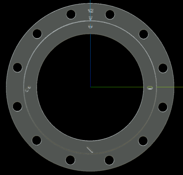
Pictured here is a sample flange with several simulated defects on the raised face.
This is how the native flange scan looks when it is first imported into FlangeVision.
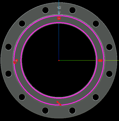
Once the automatic defect-detection algorithm is run, FlangeVision analyzes the entire gasket seating surface and places an outline around each potential defect.
The User Still Reviews Every Defect
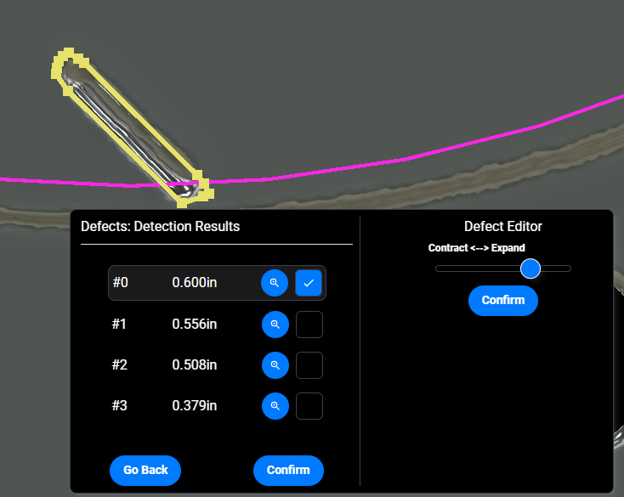
It is important not to blindly trust software. Software can make mistakes, particularly when working with real-world scan data and irregular surface conditions.
Before any detected defect is added to the final analysis, the user can inspect it individually, confirm that it is a real defect, and adjust its boundary when needed. This keeps the user in control of the inspection process rather than having the software make an unchecked decision.
Once approved, the defects are added to the FlangeVision analysis tree.
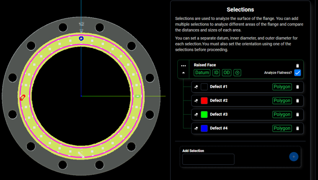
Measuring and Evaluating the Defects
FlangeVision then measures each approved defect, including its:
Circumferential location
Radial width
Maximum depth
Radial width as a percentage of the gasket seating surface
The results can then be compared against the applicable PCC-1 criteria or against custom acceptance criteria entered by the user.
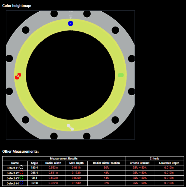
The measurements, defect locations, acceptance criteria, and results are then compiled into the FlangeVision PDF report.
For this sample flange, it took me about three minutes to:
Run the automatic detection
Review each identified defect
Adjust and approve the defect boundaries
Measure the defects
Generate the analysis results
That is a significant reduction in the time normally required to manually find, measure, evaluate, and document each indication.
Coming Soon!
We are currently testing and refining this feature, including improving the accuracy of the detection algorithm and making the review process more intuitive. We expect to release it soon.
In the meantime, we would be interested in hearing from the people who actually inspect flange faces in the field. What would make this feature most useful to you? What types of defects or field conditions should we be testing against? What is the biggest challenge you face when measuring flange defects?
Written by Tim Gaida, P.Eng.
Leave a comment or email us at info@myeng.ca
If you haven't already, join our mailing list and get regular updates, and exclusive resources tailored for professionals like you, in the industrial maintenance industry.