
ASME Raised Face Surface Finish: What the Code Requires and What Actually Matters
Flange gasket seating surfaces look deceptively simple. But the finish on a raised face has a specific code requirement, and a wide acceptable range in practice. In this article, we’ll break it down.
What the ASME Codes Specify
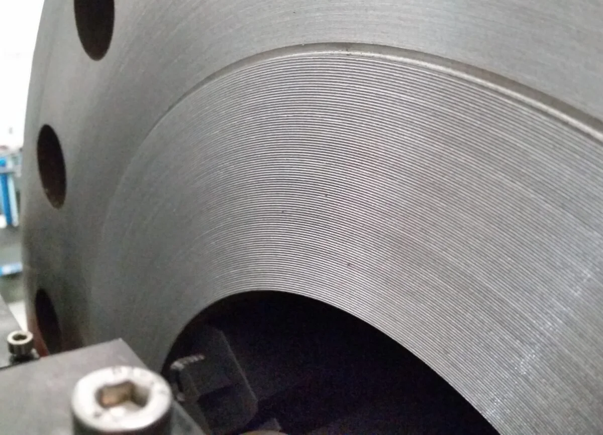
Both ASME B16.5 (section 6.4.5.3) and ASME B16.47 (section 6.1.4.2) use identical language for raised face gasket contact surfaces. The requirement is a serrated concentric or serrated spiral finish with a resultant surface finish of 3.2 µm to 6.3 µm (125 µin. to 250 µin.) average roughness (Ra). The cutting tool shall have an approximate 1.5 mm (0.06 in.) or larger nose radius, and there should be between 1.8 and 2.2 grooves/mm (45 to 55 grooves/in.).
One detail that often surprises people: both standards state that the finish “shall be judged by visual comparison with Ra standards (see ASME B46.1) and not by instruments having stylus tracers and electronic amplification.” In other words, the code-compliant method of evaluating the finish is a surface roughness comparator, used to visually confirm the surface finish, not an electronic measurement instrument. The roughness values are a target and a reference — not a measured instrument output.
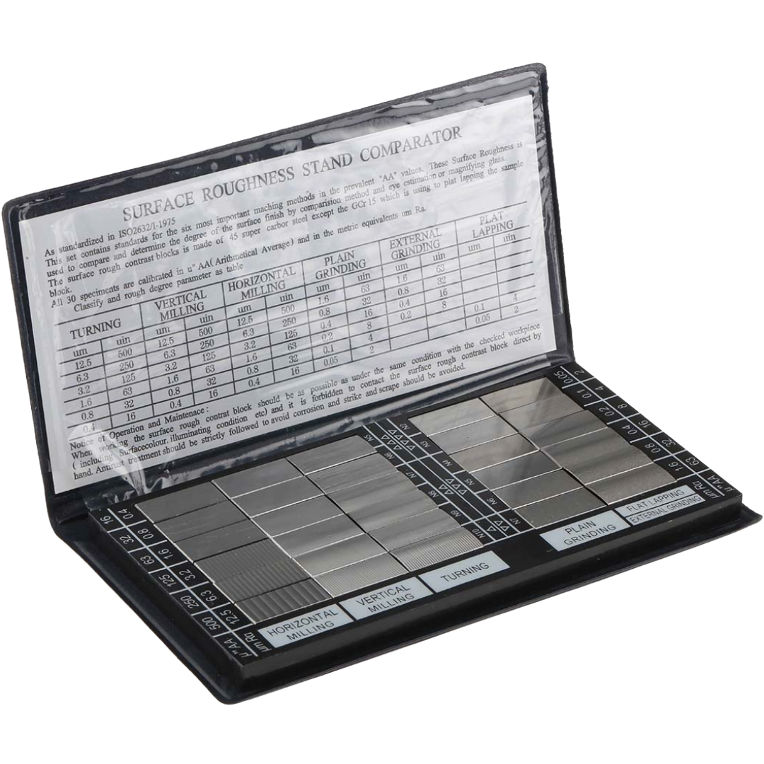
Now why would the code explicitly prohibit a more precise measurement method and specify the use of a visual comparator?
The most likely reason, although the exact reason is not explicitly defined (that I could see), is that surface finish simply isn't a variable that warrants a precision inspection, which would be achieved by using something like a stylus profilometer.
Visual comparison with a reference standard is entirely acceptable and fit for purpose: it quickly confirms the finish is in the right ballpark and lets the inspector move on to things that matter more, such as flange flatness, defect measurement, ovality, flange alignment, bolt load, and gasket condition.
More quantitative is not always more better.
Adding measurement precision beyond what the application requires costs time without improving the outcome, and in an inspection workflow, that time has real value.
It's also worth noting the distinction between Ra (arithmetic average roughness) and RMS (root mean square roughness, also called Rq), which is how surface finish is commonly discussed in the field.
Strictly, the two are not identical. For a typical machined surface, RMS is about 1.11 times Ra, so the code’s 125 to 250 µin Ra works out to roughly 139 to 278 µin RMS. In practice, though, nobody applies that conversion. Inspectors read the face against RMS comparators marked in the familiar round numbers and call a 125 Ra spec a 125 RMS finish. So for the rest of this article I will use the field RMS values, 63, 125, and 250, and treat them as interchangeable with the code’s Ra numbers.
Concentric vs. Spiral Serrations: Both Are Acceptable!
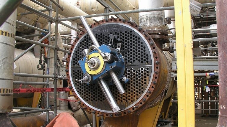
The code permits either a serrated spiral or serrated concentric pattern, and both look similar at a glance. The difference is in how the flange facing machine moves:
Serrated spiral: The tool feeds continuously and gradually across the face in one unbroken helical path. The result looks like concentric rings under a light source, but is actually a single spiral groove from the bore to the OD (or vice versa).
Serrated concentric: The tool is indexed — stepped discretely between passes — producing true closed rings at each radius. Each groove is a separate, closed circle.
Both produce the same groove geometry and finish quality when done correctly. Spiral is the more common method in practice, but concentric finishing is a legitimate alternative, particularly on specialized facing machines or where the setup or client specifically calls for it.
The Practical Surface Finish Range Commonly Used Is Actually Wider
According to what we have learned from conversations with people in the industry, the code's 125–250 window is the target, but finishes anywhere in the range of 63 to 250 RMS are generally considered acceptable without much scrutiny. Often inspectors will even accept 500 RMS. The reason comes down to what the finish is actually doing.
The serrations aren't a sealing surface — they're a bite surface. The peaks and valleys of the serrations create high local stress concentrations when the gasket is compressed, helping it bite into the gasket, create a seal and grip the gasket to resist blowout.
The joint integrity, or practically speaking if the flange will leak, is not dominated by the surface finish. What matters far more is overall gasket stress — the total compressive load distributed across the gasket contact area, governed primarily by the bolt load and flange stiffness.
A textbook perfect flange face, that is improperly bolted, will leak long before a flange with a surface finish slightly outside of the allowable range causes any problems.
What FlangeVision Does (and Doesn't) Inspect
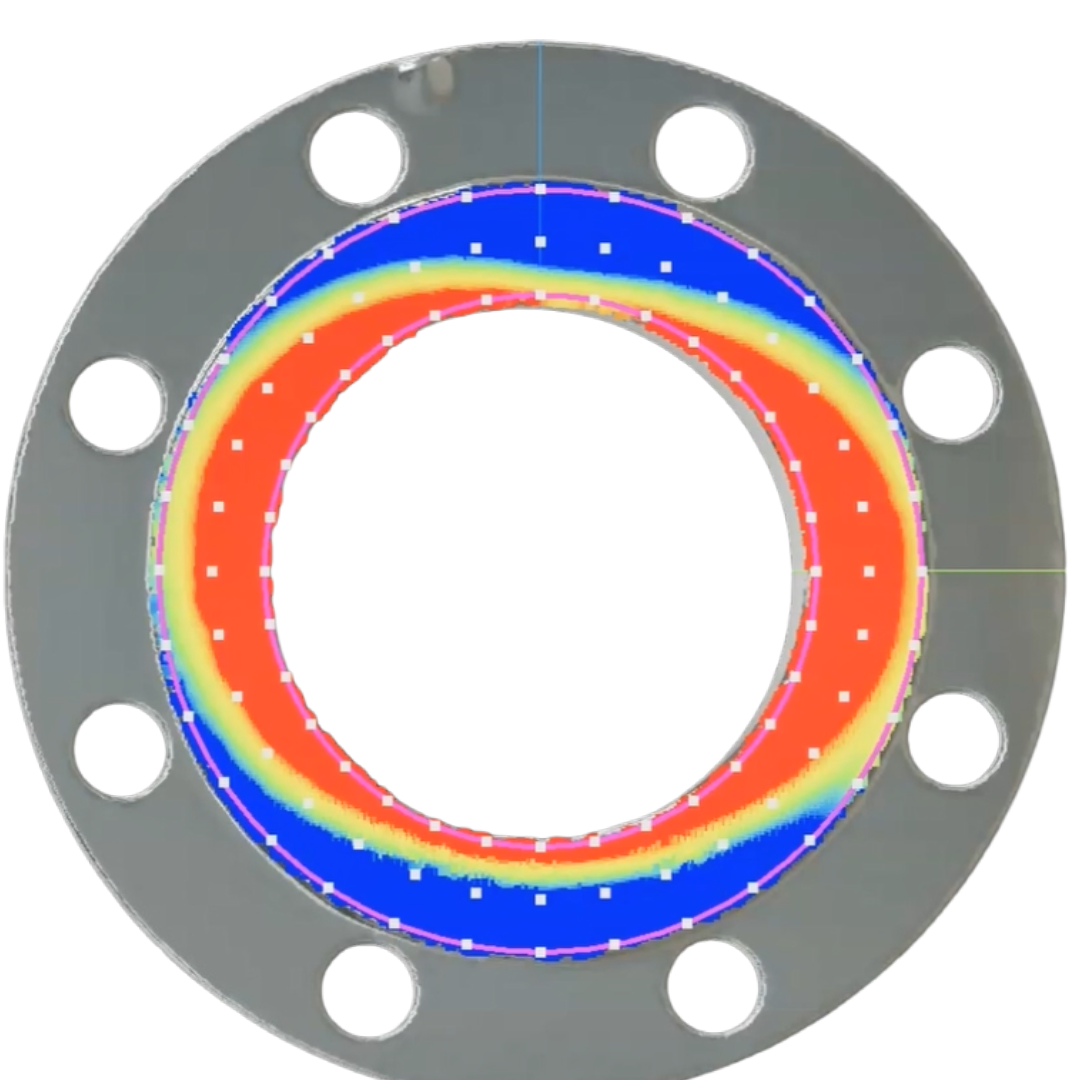
Our FlangeVision software imports 3D scan data for fast and precise flange inspection. We typically recommend high precision blue light laser scanners for their combination of accuracy and speed — and while these scanners are often capable of high-resolution capture (meaning capable of capturing very small features on the flange being scanned), maximizing the scanners resolution is often not desirable for performing the standard flatness and thickness measurements required in a basic flange inspection.
Surface finish measurement is a different matter entirely. Resolving 125–250 RMS features in 3D would require submicron point spacing across the entire face, making scan resolution, data volumes, and processing time completely impractical. FlangeVision does not directly measure surface finish.
This is also consistent with the code's own intent: B16.5 and B16.47 both specify that the finish is assessed visually, not by instrument. The appropriate tool for a finish check is a surface roughness comparator — not a 3D scanner.
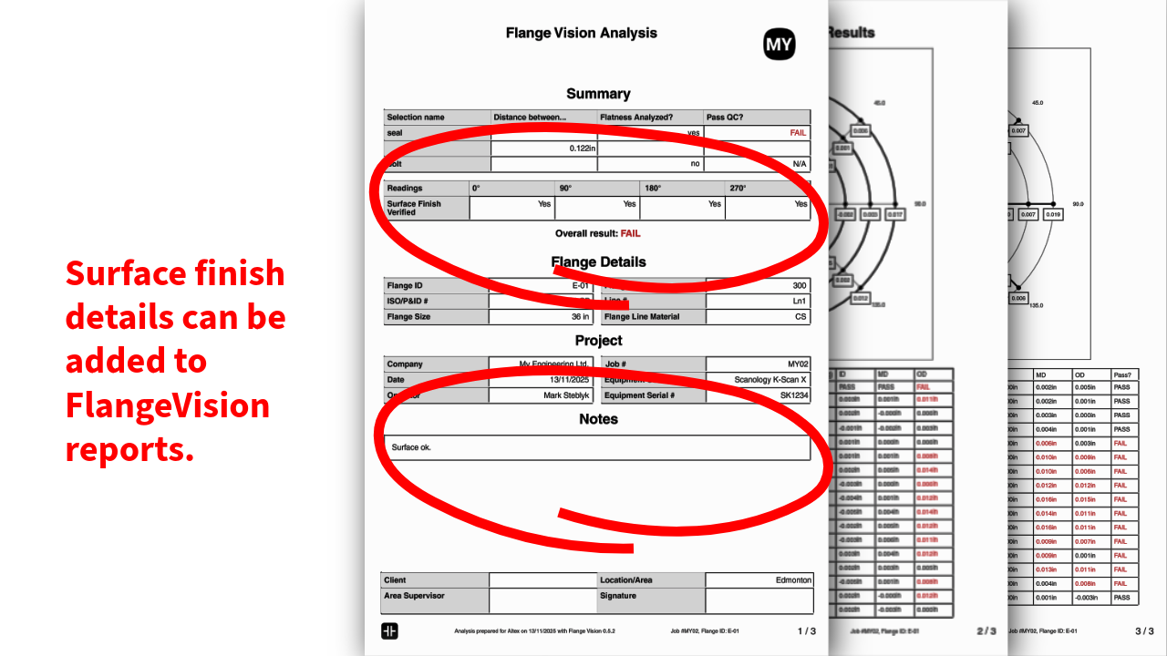
What FlangeVision does provide is a place for that data. If a surface finish measurement has been taken separately, the result can be recorded and included in the FlangeVision inspection report alongside the dimensional findings from the scan. One report, complete traceability.
The information in this article is provided for general reference purposes only. Always consult and apply the currently approved, project-specific edition of the relevant design code or standard. Codes and standards are revised over time, and the requirements applicable to your project may differ from what is described here. While every effort has been made to ensure accuracy, errors and omissions may exist. FlangeVision and its contributors accept no liability for any decisions made, or actions taken, in reliance on the content of this article.