
How it Works
It all starts with a scan. FlangeVision is able to automatically perform a detailed analysis on input 3D scan data in the form of .STL files. The FlangeVision workflow is divided into two simple steps: Analyze, and Report.
Scan
Modern scanning tools have made the process of measure flange flatness, fast, portable, and practical. Setup takes minutes, scanning is intuitive and the results are highly accurate. And most importantly—it provides a complete digital picture of a flange, not just a handful of measurement points.
FlangeVision will accept STL mesh files from any 3D Scanner. Click here, for more information about selecting the right scanner for flange inspections.
-
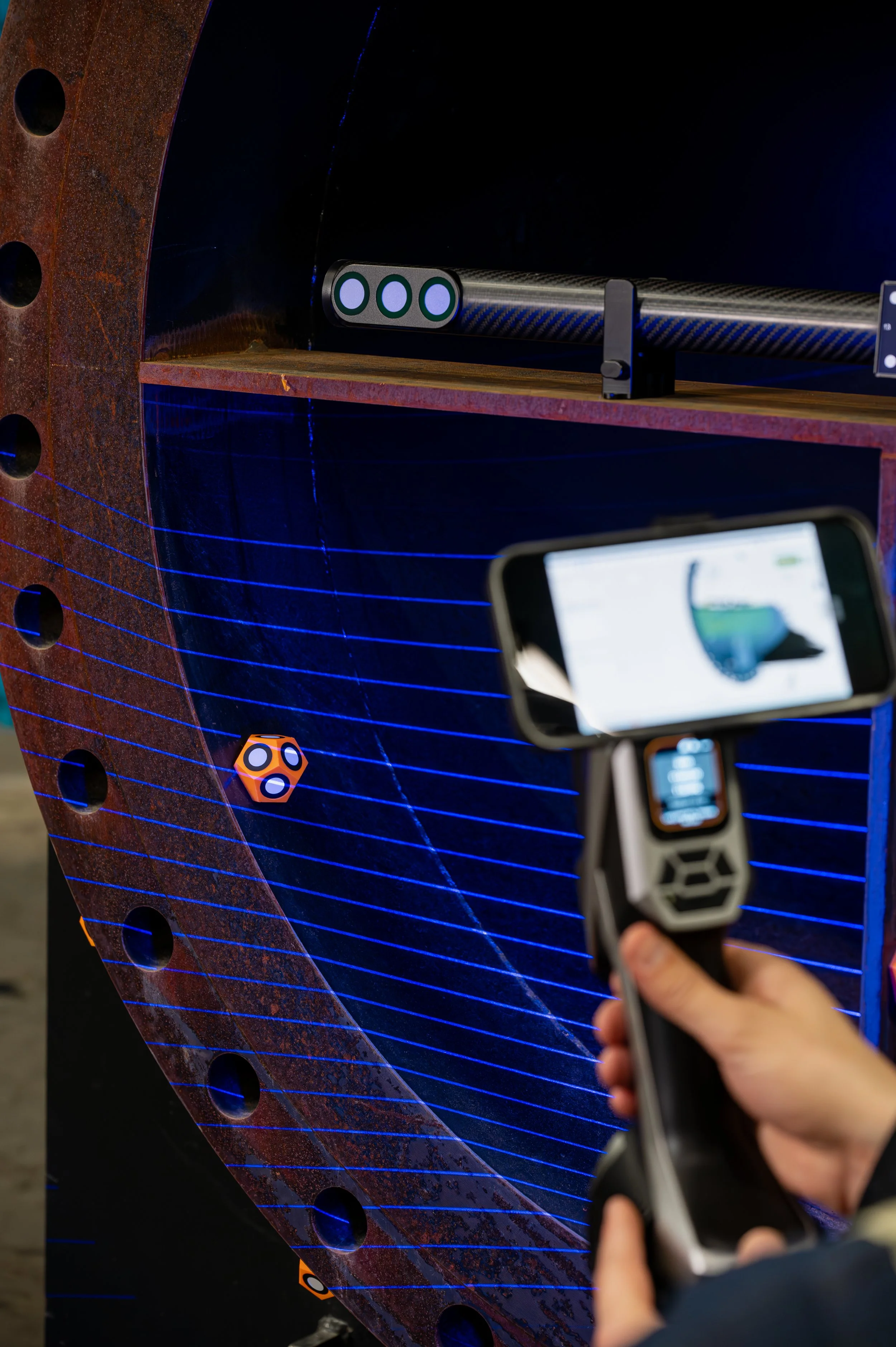
Before scanning begins, small reflective markers are placed around the flange. These markers are reference points for the scanner to help it understand where it is in space as you move around the object.
For larger flanges (36” and larger), we recommend using scale bar(s) to correct for volumetric drift. The scale bar provides a known physical reference length that the scanner uses to correct for this drift (small accuracy errors over larger distances), and ensures measurements stay within tight tolerances required for flange inspections.
Applying a light dusting of scanning spray to the surface will aid in the scanning process. The spray creates a thin, matte coating that helps the laser “see” the surface more clearly.
-
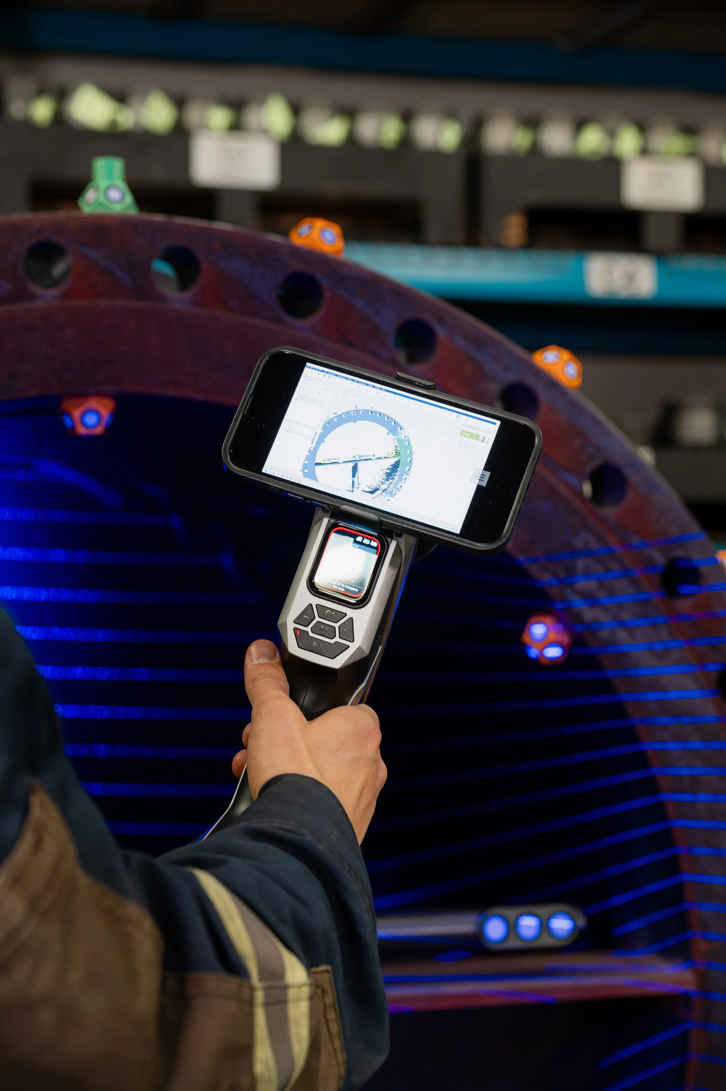
Scanning the flange is as simple as moving the scanner over the flange face and back side of flange, effectively “painting” it with laser lines.
Ensure to capture the entire flange, as the data will be used in the analysis process to measure flatness, and thicknesses of the raised face and overall flange thickness.
-
After scanning is complete, the raw data includes everything the scanner saw—including unwanted areas such as background objects and attached piping which won’t be analyzed.
Using the Scanning software, remove any unwanted objects from your scan data. Being thorough will result in clean data which will present well on your final FalngeVision reports.
The cleaned scan data is now converted into a 3D mesh and exported in an “.STL'“ Format. This step turns the raw point data into a polygonal surface model—a digital replica of the flange. Save this file to an easy-to-access location on your computer for importing into FlangeVision.
How to scan a flange for inspection in FlangeVision
Analyze
To start; import the scan in the form of an STL file. Files can be imported in either metric or imperial units. Alternatively, previously-saved FlangeVision projects, can be re-opened.
Once the STL file is imported, the analysis screen appears. A FlangeVision analysis starts with one or more “Selections”. These are regions on the scanned mesh that have been selected by the user for analysis- for instance on a single flange one can select the sealing surface, bolt surface, and rear surface of the flange.
-
To assign a selection we use a 3D geometry flood-fill algorithm, starting from the initial point the user clicks on the mesh. This algorithm is designed to follow along flat surfaces and not cross over edges, effectively allowing the user to select any flat surface on the mesh with a single click.
-
Once a datum selection has been made, the mesh points contained within, are used to establish a datum plane to use for reference when defining the ID, MD, and OD (inner diameter, middle diameter, and outer diameter) measurement circles. At this point the user can select the desired location of the ID and OD circles; our software will then automatically pick a set of measurement points along these circles later on.
-
In addition to these circular measurements, FlangeVision also offer the ability to define additional line measurements. The user can specify as many pass-partition lines as they'd like.
FlangeVision Analysis
Report
This is the moment when FlangeVision gets to really flex it's muscles! FlangeVision will automatically prepare the following:
Distance-between-selections chart
Circumferential and Radial flatness measurements for each selection
Measurements for each pass partition measurement line
Diagrams illustrating all of the above
Flatness color-maps for each selection
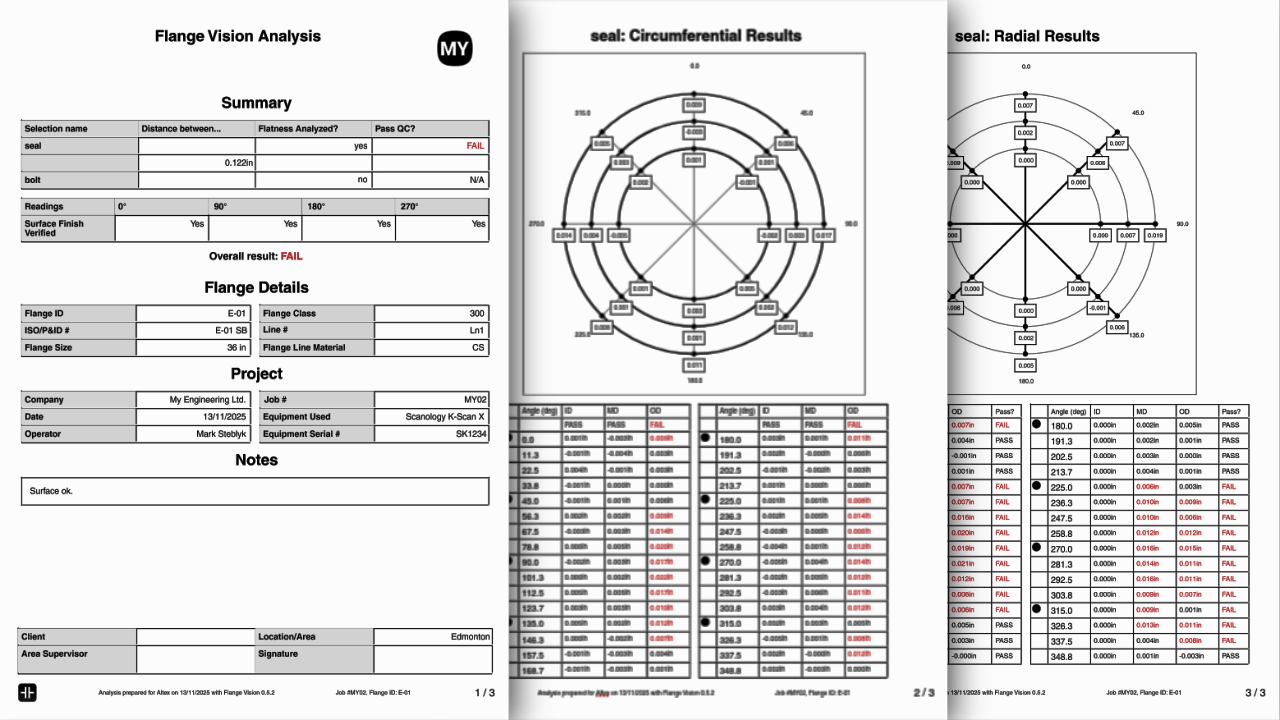
All of the results computed by Flange Vision are evaluated against built-in or user-specified pass/fail criteria; each measurement is flagged as passing or failing. An overall pass/fail result is also prepared, streamlining your qualification process.
FlangeVision will automatically produce a formatted PDF file, containing renders of the STL file from various angles, tables of circumferential and radial measurement data, pass-partition line measurements (where applicable), a table of distances between each of the selected faces, and any other manually-included information from the user like line numbers, job details, and notes.
-
For each selection, the app starts with the reference datum plane that the user picked and establishes a separate datum plane for each of the ID, MD, and OD measurement circles using only the mesh points in near proximity to these circles.
This helps to ensure that overall flange sealing surface concavity or convexity doesn't introduce an offset in the circumferential flatness measurements- (those kinds of error are captured by the radial analysis) and is also analagous to a technician in the field setting a datum on each circumferential flatness measurement prior to taking their readings.
Once these datum planes are defined, the software takes measurements of the meshes displacement from the datum at regular intervals, and evaluates each measurement against the selected pass/fail criteria. -
The radial measurements for each selection are also prepared using the datum planes defined in the previous step. This time however, only the ID datum plane is used.
All radial measurements are taken relative to this datum- this would be analogous to a measurement in the field being zeroed on the internal diameter- and then distance measurements are computed relative to that. moving outwards from the ID ring to the OD ring. -
Finally, for each selection the pass-partition line measurements are computed. These measurements are taken at regular intervals over the lines specified by the user, sparing them the laborious task of manually selecting each individual point they'd like to measure.
The algorithm starts by working out the straight-line distance and dividing it up into regular intervals; it then computes the displacement of the mesh from the point, and similar to the radial and circumferential flatness measurements compares this value to the selected pass-fail criteria.
FlangeVision Reporting
Inspect a Flange in 10 Minutes!
In this time lapsed video, we showcase the speed and simplicity of Flange inspection using 3D Scanning and FlangeVision.