
3D Scanning a Flange: A simple, step-by-step workflow
When people hear “3D scanning,” it can sound complex or highly technical. In reality, modern scanning tools have made the process surprisingly fast, portable, and practical—even out in the field.
In this article, we’ll walk through a real-world example: inspecting a flange for flatness using a handheld laser scanner. Along the way, we’ll highlight best practices, and—most importantly—explain why each step matters.
For the purposes of this article, we used the Scanology KScan-X scanner. If you are using another make and model of laser scanner, these steps are similar.
The Goal
The objective is simple: capture an accurate digital model of a flange so it can be inspected for flatness and other features using FlangeVision.
To do this, we use a handheld laser scanner. Instead of measuring just a few points manually on the flange face, the scanner captures thousands of data points across the entire surface.
Step 1: Placing Reference Markers
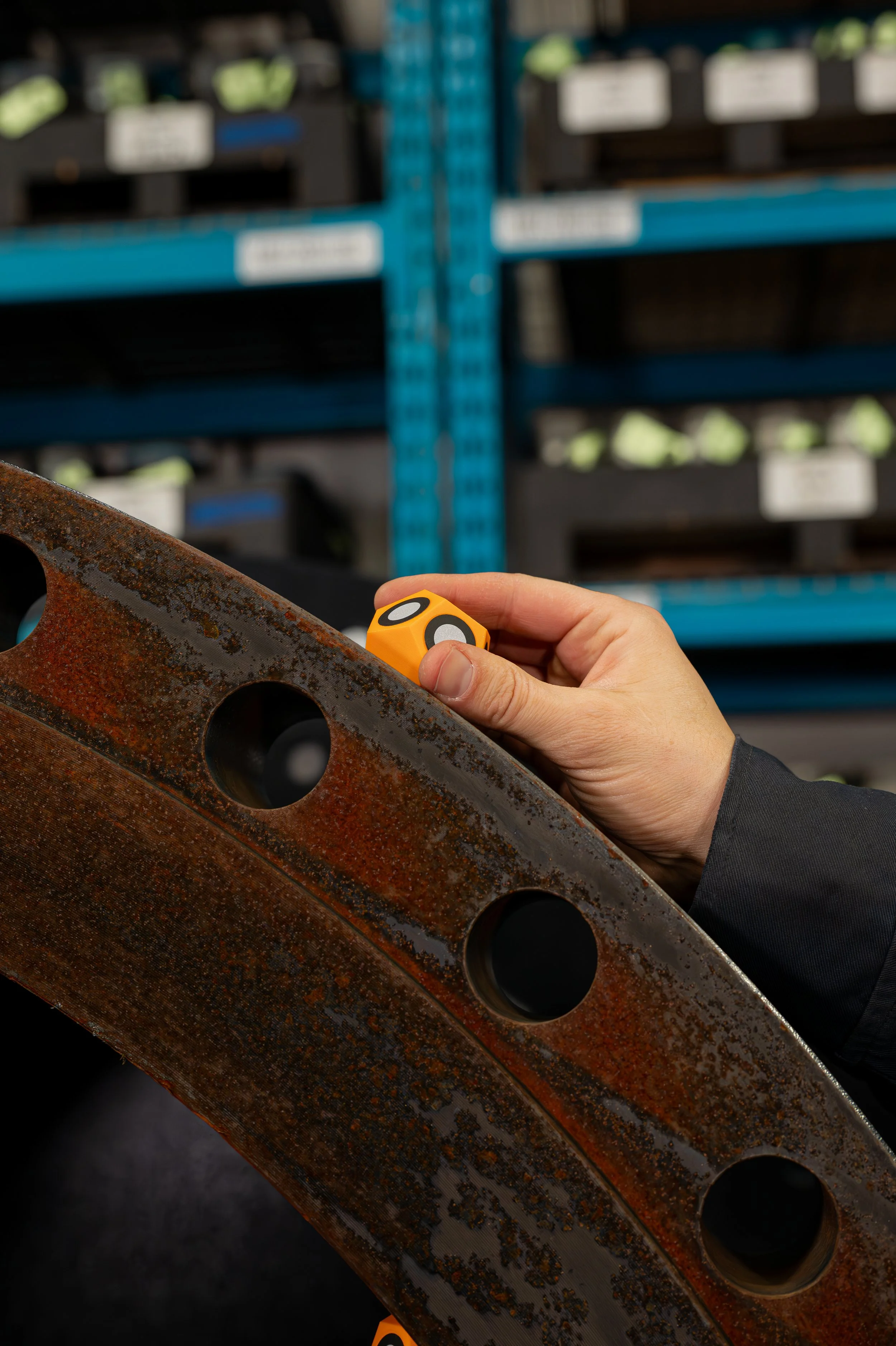
Before scanning begins, small reflective markers are placed around the flange. These markers are reference points for the scanner to help it understand where it is in space as you move around the object.
Best practices:
Space markers roughly 6–12 inches apart, depending on your scanners field of view.
Place them “randomly” around both:
The outer diameter (OD)
The inner diameter (ID) when possible
Add a unique shaped reference marker at a known position (e.g., 12 o’clock)
Adequate marker placement, ensures the scanner doesn’t lose tracking during scanning, and reduces errors when splicing multiple scans together.
Pro tip:
Using magnetic marker dice (instead of stickers) where possible, as this will dramatically speed up setup and tear down time.
For details about marker dice and scanning accessories Click Here.
Step 2: Adding a Scale Bar for Accuracy
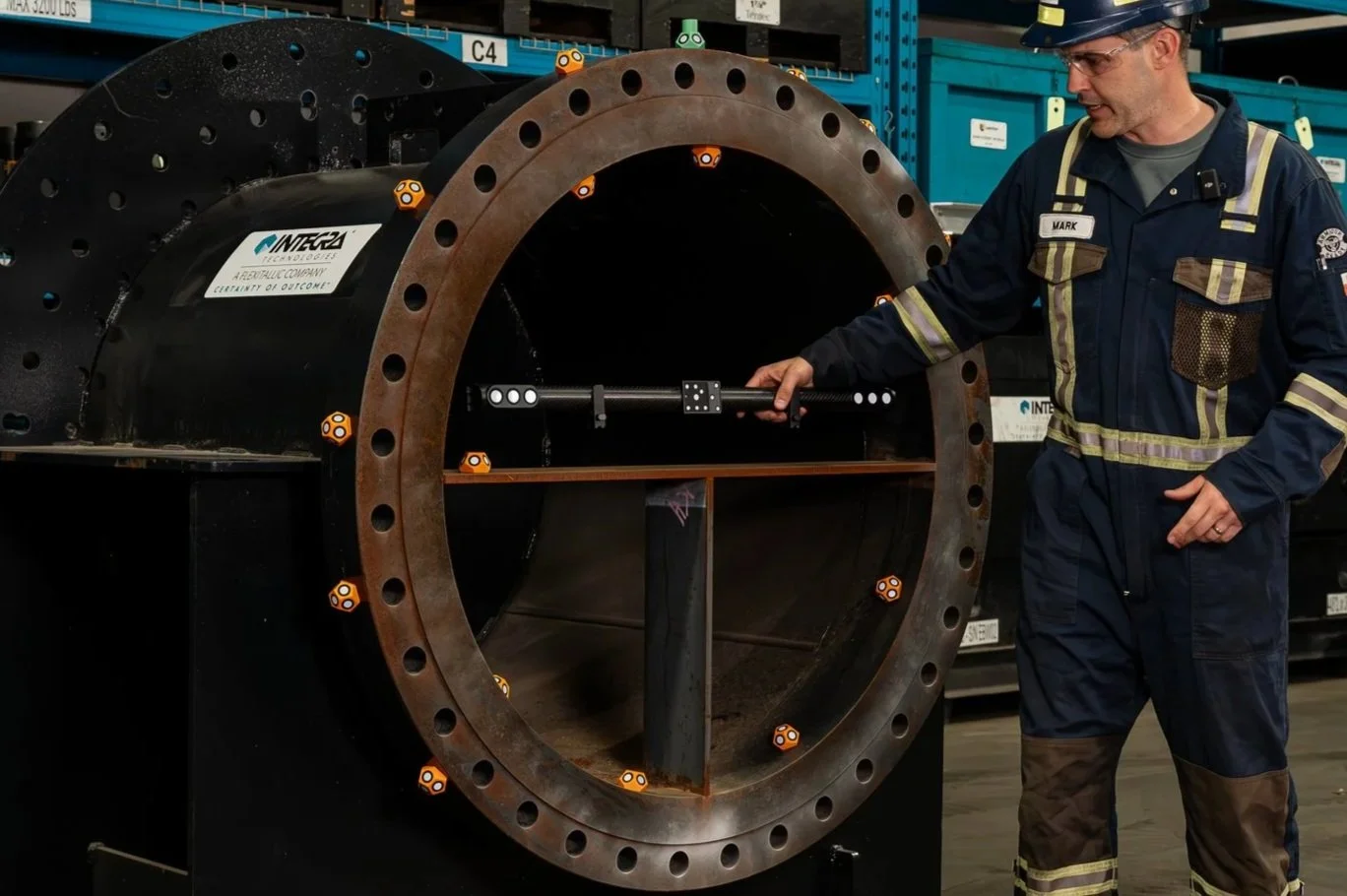
For larger flanges (36” and larger), we recommend using scale bar(s) to correct for volumetric drift. The scale bar provides a known physical reference length that the scanner uses to correct for this drift (small accuracy errors over larger distances), and ensures measurements stay within tight tolerances required for flange inspections.
Step 3: Applying Scanning Spray
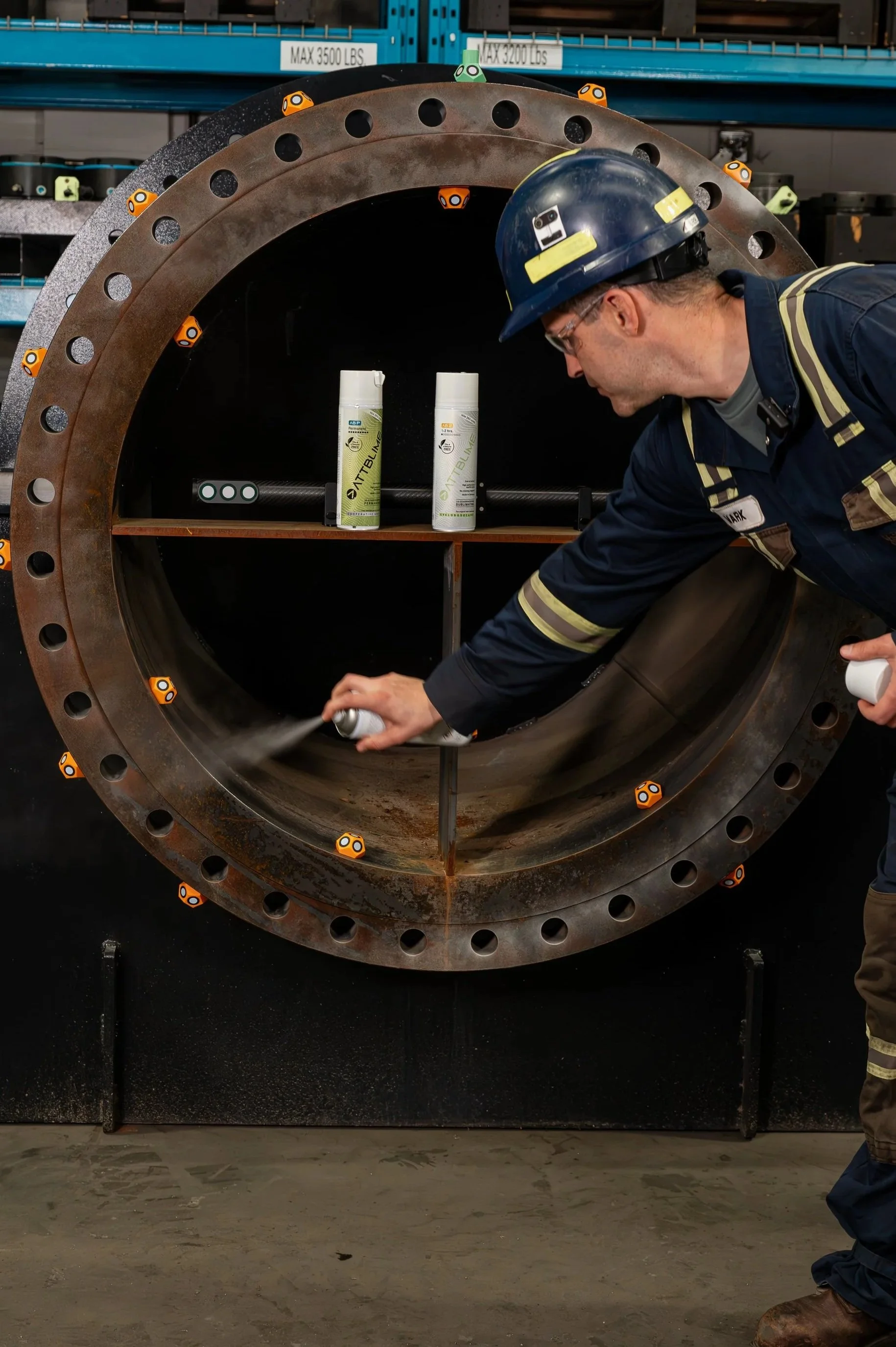
A light dusting of scanning spray is applied to the surface. The spray creates a thin, matte coating that helps the laser “see” the surface more clearly. This improves laser reflectivity, p
revents issues created by shiny or dark surfaces, and results in cleaner, more accurate data. Most importantly, applying scanning spray results in a faster scanning process without frustration.
We use AttBlime Scanning Spray
Step 4: Scanning the Markers
Before capturing the full Flange geometry, the scanner first reads all the markers.
The scanner maps out the positions of all markers to establish a tracking framework. This step creates a stable coordinate system for the scanner and ensures smooth, continuous scanning.
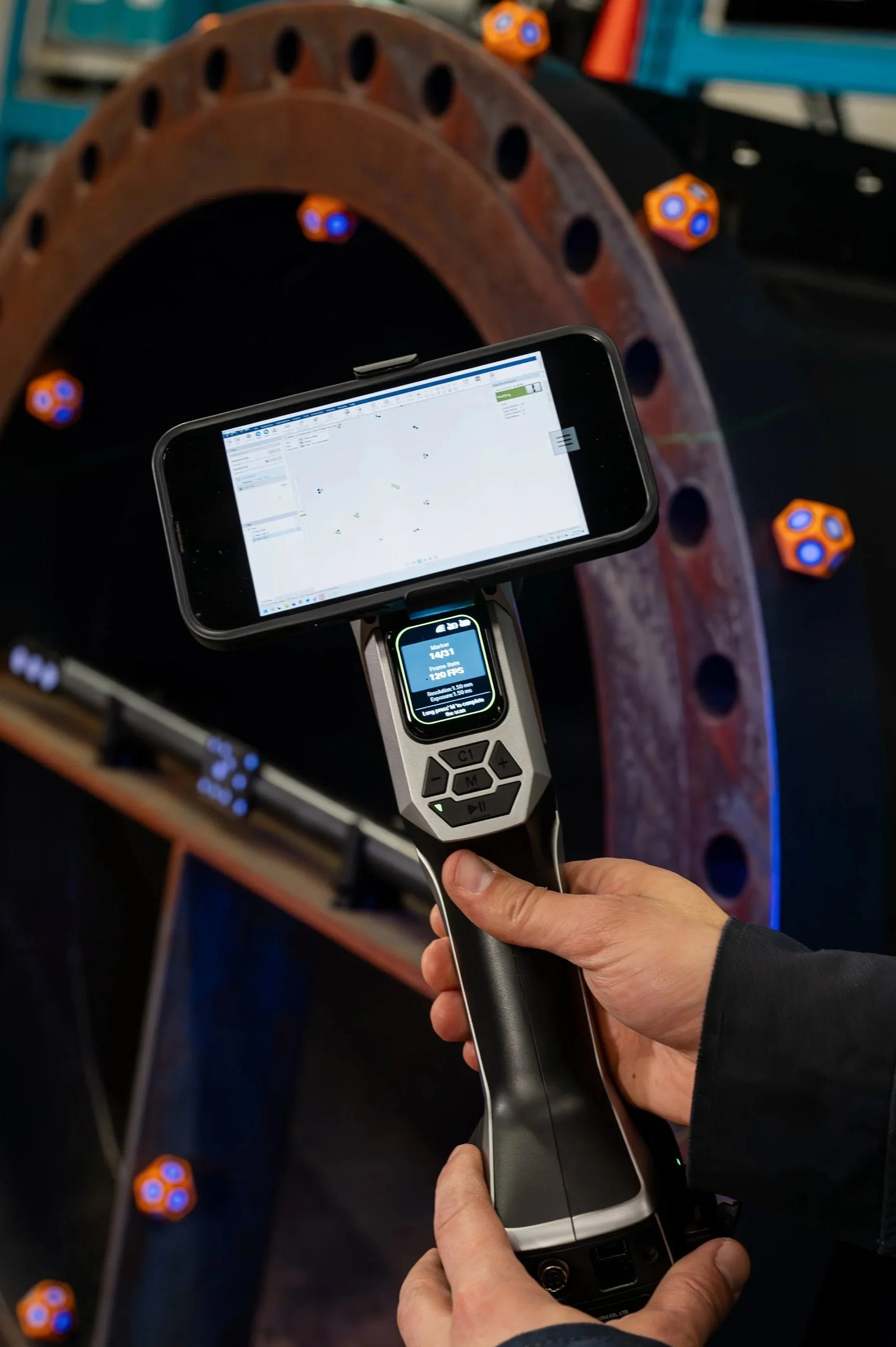
Step 5: Capturing the 3D Scan
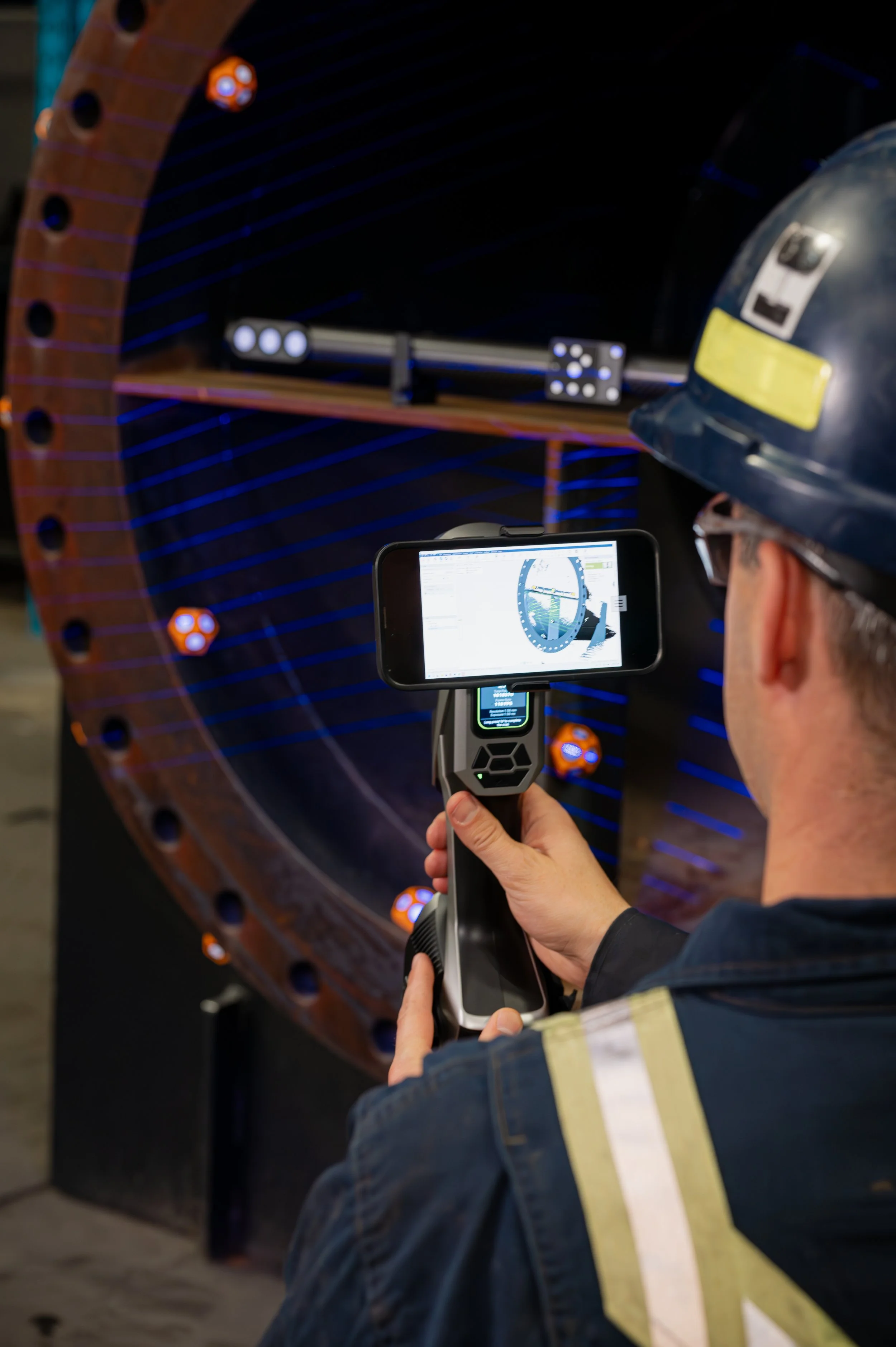
Now comes the main event: scanning the part. The operator moves the scanner over the surface, effectively “painting” it with laser lines.
Best practices:
Move steadily and smoothly
Cover all critical areas:
Sealing surface (flange face)
Back face
Bolt face
Internal partitions (if applicable)
Capture enough geometry for all required measurements (e.g., thickness)
*Complete coverage ensures nothing important is missed.
Once coverage is sufficient, the scan is finalized.
Step 7: Cleaning Up the Data
After scanning is complete, the raw data includes everything the scanner saw—including unwanted areas such as background objects and attached piping which won’t be analyzed.
Using the Scanning software, remove any unwanted objects from your scan data. Being thorough will result in clean data which will present well on your final FalngeVision reports.
Step 8: Creating the Mesh & Exporting
The cleaned scan data is now converted into a 3D mesh and exported in an “.STL'“ Format. This step turns the raw point data into a polygonal surface model—a digital replica of the flange. Save this file to an easy-to-access location on your computer for importing into FlangeVision.
Final Thoughts: The Big Takeaway
Modern 3D scanning is no longer complicated or slow. With the right setup and workflow, setup takes minutes, scanning is intuitive and the results are highly accurate. And most importantly—it provides a complete digital picture of a flange, not just a handful of measurement points.
3D Scanning is a powerful tool in today’s engineering and inspection workflows.