
How Repeatable Is FlangeVision?
When you measure the same flange twice, you should get essentially the same answer. That sounds obvious, but with 3D scanning there are a lot of variables involved. The scanner may be repositioned. Targets and scale bars may be moved. Lighting can change. The operator may approach the surface from slightly different angles. And in the field, you may not always have perfect access to every surface.
So before relying on a digital flange-inspection workflow, we wanted to answer a basic question: How repeatable are the results?
We designed a practical repeatability study around FlangeVision using the same 24-inch NPS Class 300 weld-neck flange, repeatedly scanning and analysing it under several different conditions. Twenty scans were completed and recorded, with 19 retained for the statistical repeatability analysis.
Key takeaway: Across the valid test conditions, FlangeVision repeatedly produced GSS flatness results in the hundredths-of-a-millimetre (1/2540 of an inch) range, while also revealing practical limits around direct sunlight, scan coverage and partial scanning.
What does "repeatability" mean?
Repeatability is different from accuracy.
Accuracy asks whether a measurement is equal to the true value.
Repeatability asks whether you get the same result when you measure the same thing again.
For this study, we were interested in repeatability. We repeatedly measured the same physical flange and looked at how much the reported measurements changed from scan to scan.
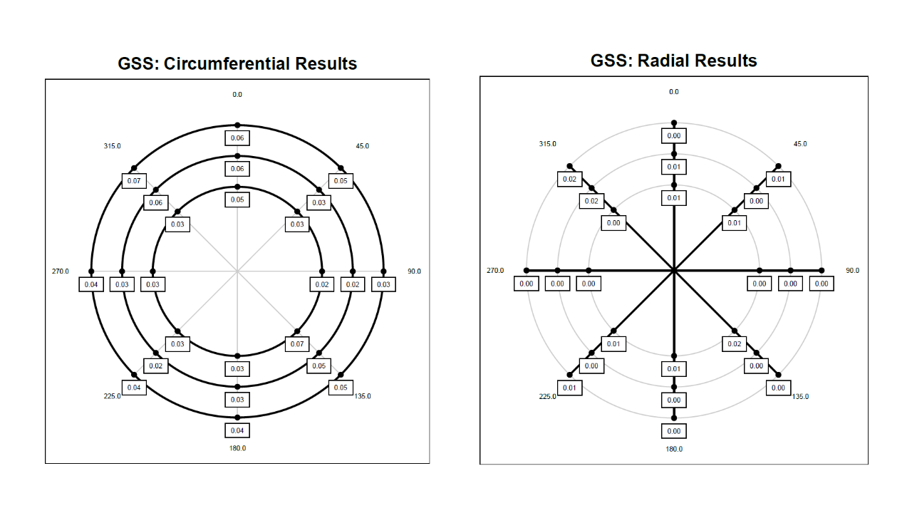
The study tracked eight reported quantities: two datum-distance measurements and six gasket sealing surface, or GSS, measurements. The GSS was evaluated at its inner, middle and outer regions in both the circumferential and radial directions.
How we set up the test
The flange was suspended vertically so the same part could be scanned repeatedly from realistic working positions. Optical markers were used so the scanner could track its position around the flange, while scale bars provided a dimensional reference. The marker and scale-bar configurations were deliberately re-established or changed between selected scans so the test included normal setup variation rather than one perfectly fixed laboratory arrangement.
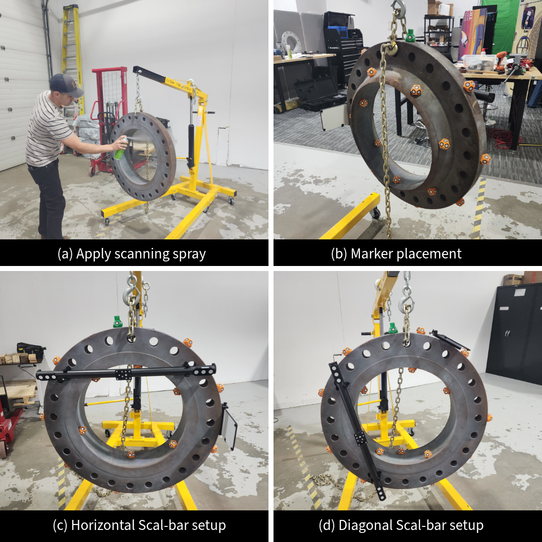
Test setup used during the study: scanning-spray application, optical markers, and two scale-bar configurations.
The baseline: repeated indoor scans
We began with six full indoor scans.
Across those scans, the six GSS flatness measurements were tightly grouped. The average standard deviation across those measurements was approximately 0.010 mm (0.0004 inches), with the most variable individual GSS measurement having a standard deviation of approximately 0.019 mm (0.0007 inches).
In simpler terms, when we repeatedly scanned and analyzed the same sealing surface, FlangeVision continued to report very similar geometry.
That is important because a useful inspection system needs more than a high-resolution scanner. The complete workflow - scanning, mesh generation, surface analysis, angular alignment and reporting - needs to produce consistent results.
What happens when the setup changes?
Field inspection is rarely as controlled as a laboratory test.
We therefore repeated scans on different days and deliberately varied the scale-bar setup. Those multi-day scans produced the lowest variability of any condition tested, with an average GSS standard deviation of approximately 0.006 mm (0.0002 inches).
The takeaway is not that changing the setup somehow improves the measurement. Rather, we did not observe a material loss of repeatability across the multi-day and scale-bar configurations that we tested.
That is encouraging because it better represents how the system will actually be deployed.
Can we scan outside?
We also tested outdoor scanning.
In shade, the retained scans showed repeatability comparable to the indoor baseline, with an average GSS standard deviation of approximately 0.012 mm (0.0005 inches).
Direct sunlight was a different story.
Under the direct-sun conditions we tested, we were unable to obtain usable scans. For practical field work, our conclusion is straightforward: scan indoors, in shade, or shield the inspection surface from direct sunlight.
The outdoor testing also reinforced another important lesson: scan coverage matters. One shade scan returned FAIL and was excluded from the repeatability analysis because part of the flange was not adequately captured. Another shade scan had missing readings at two circumferential locations.
What about partial scans?
This was one of the more interesting parts of the study.
In some field situations, the gasket sealing surface may be accessible while other portions of the flange are difficult to capture. We wanted to understand whether capturing the GSS completely, while only partially scanning the sides and back of the flange, would materially change the result.
We performed six partial scans, each paired with a corresponding full scan.
The partial scans remained highly repeatable, with an average GSS standard deviation of approximately 0.014 mm (0.0006 inches), compared with approximately 0.010 mm (0.0004 inches) for the full-scan baseline.
But the paired comparison revealed something worth investigating.
The radial measurements showed a small, consistent positive shift, averaging approximately:
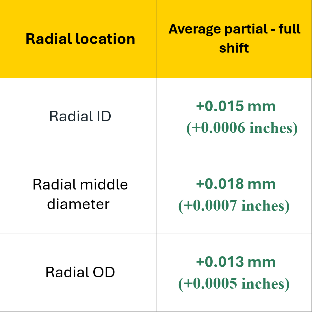
The radial measurements showed a small, consistent positive shift, averaging approximate values as detailed in this chart.
Those differences are small, but because they moved in the same direction rather than appearing randomly, we do not want to dismiss them as noise.
There is also an important qualification: the scale-bar location changed between the paired full and partial scans. That means this study cannot conclusively say that partial scanning itself caused the difference.
Why might scan coverage matter?
One hypothesis is the amount of multi-angle laser coverage used to build the surface.
A 3D scanner does not simply take one picture of a surface. During a good scan, the same geometry is captured repeatedly from different directions. Those observations are combined to develop the final point cloud and mesh.
Even when the scanner's nominal resolution remains unchanged, a surface that receives less coverage from different angles may not be reconstructed in exactly the same way.
That could help explain the small radial shift we observed in the partial scans.
At this stage, however, that is a hypothesis, not a conclusion. A future test would need to hold the scale-bar arrangement constant while deliberately varying scan coverage to isolate that effect.
A subtle source of variation: angular alignment
FlangeVision reported GSS values at 32 angular sample positions around each measurement ring. To put those sample positions in the same place from scan to scan, the flange is first oriented to a top-dead-centre, or TDC, reference.
In this study, the operator set TDC visually using the corner of a retained marker. A very small difference in the point selected can rotate the 32 sample locations slightly around the physical flange. On a real surface, that means the software may sample a slightly different local high or low spot even when the underlying scan geometry is essentially the same.
That matters because a repeatability study measures the complete workflow, not just the scanner. Some of the scan-to-scan scatter in the tabulated ring values may therefore come from angular registration rather than scanner measurement noise.
This type of registration difference should add random scatter. It would not be expected to create the consistent positive radial shift seen in the partial-scan comparison.
Engineering lesson: repeatability belongs to the whole measurement process - scanner, scan coverage, setup, registration, analysis and reporting - not to one specification on a scanner datasheet.
What did we learn?
· FlangeVision demonstrated strong repeatability. Repeated measurements of the gasket sealing surface remained tightly grouped across indoor scans, different days, changing setups and outdoor shade.
· Field conditions matter. Direct sunlight prevented us from obtaining usable data under the conditions tested, while incomplete surface coverage produced unreliable results.
· Partial scanning may be workable, but scan quality still matters. Partial scans remained highly repeatable and generally agreed closely with full scans, but the small directional shift in the radial measurements deserves further investigation.
· The workflow itself contributes to variation. Visual TDC alignment can shift the exact 32 sample positions slightly from scan to scan, adding scatter that is not necessarily scanner noise.
· Datum selection deserves attention. The outside-face datum-distance measurement showed more variation than the GSS flatness measurements and is an area where we can continue refining the workflow.
And perhaps most importantly: repeatability is not the same thing as accuracy.
This study tells us that FlangeVision can repeatedly produce very similar measurements of the same flange. It does not establish absolute measurement accuracy against a calibrated reference system. Establishing that would require a separate comparison against a known reference instrument.
Where do we go from here?
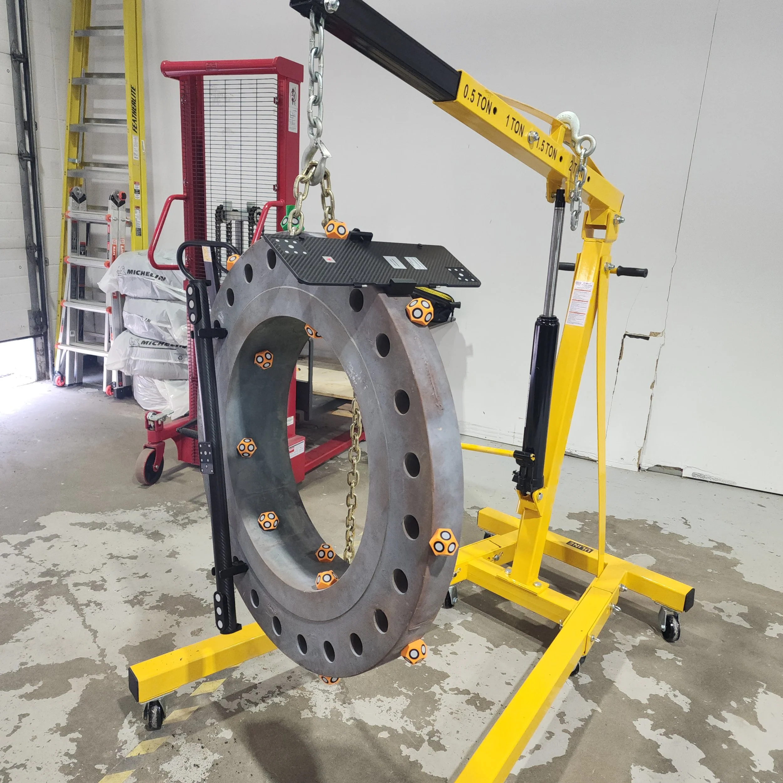
The purpose of testing is not simply to prove that something works. It is to understand where it works, how well it works, and where the limitations are.
Our next steps include further controlled testing of partial scans with scale-bar placement held fixed, making TDC alignment more deterministic, refining the outside-face datum measurement, and eventually comparing against reference measurement equipment to evaluate absolute accuracy.
For us, that is an important part of developing FlangeVision: not just building inspection software, but understanding the complete measurement process behind the result.