
ASME B16.5 vs. B16.47: Which Standard Applies to Your Flange?
If you've spent any time specifying or inspecting pipe flanges, you've encountered both ASME B16.5 and ASME B16.47. At first glance the question of which one applies seems simple — it's just about size, right? That's mostly true, but once you dig into the details, the two standards diverge in ways that matter well beyond the nominal pipe size stamped on a flange. Here's what every engineer and inspector should know.
The Size Split: NPS 26 Is the Dividing Line
The most fundamental distinction is the size range each standard covers:
ASME B16.5 covers flanges and flanged fittings from NPS ½ through NPS 24.
ASME B16.47 picks up at NPS 26 and runs through NPS 60.
There is no overlap. A flange marked NPS 24 lives entirely within B16.5; a flange marked NPS 26 belongs to B16.47. These are not interchangeable standards — dimensions, bolt patterns, and pressure ratings are defined independently in each document.
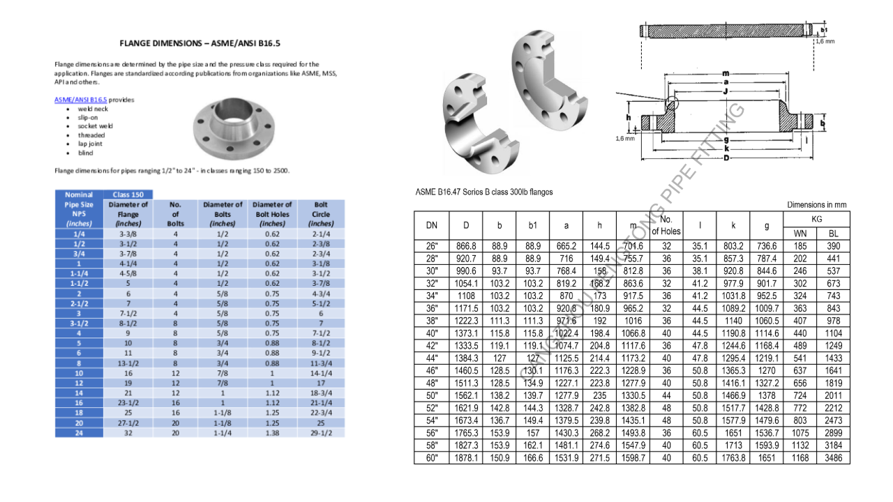
Nominal Pipe Size listing for ASME B16.5 & B16.47: Source - Fitting-flange.com
Pressure Class Range: B16.5 Reaches Higher
Both standards organize pressure capacity using the familiar “Class” designation, but the available classes are not the same.
B16.5 covers Classes 150, 300, 400, 600, 900, 1500, and 2500. Class 2500 is available for sizes up to NPS 12; Classes 150 through 1500 extend to NPS 24.
B16.47 covers Classes 75, 150, 300, 400, 600, and 900 — and stops there. Class 1500 was considered during the standard’s development but was dropped due to lack of industry demand for large-diameter flanges at that pressure level. Class 2500 is not covered at all.
The practical takeaway: if your process requires Class 1500 or 2500 service, you are in B16.5 territory by definition, which also means you are limited to NPS 24 and smaller.
What happens when you genuinely need a large-diameter, high-pressure flange — say NPS 30 at Class 1500 pressures? Neither standard covers it. In those situations the flange must be custom engineered, typically designed in accordance with ASME Section VIII Division 1 (Appendix 2 covers the bolted flange design methodology most commonly used). This moves the work from a standard lookup into a formal pressure vessel engineering exercise. If you find yourself in that territory, My Engineering Ltd. — our sister company — provides that kind of custom pressure equipment engineering work.
Class 75: B16.47’s Low-Pressure Rating You Won’t Find in B16.5
On the low-pressure end, B16.47 introduces something B16.5 doesn’t have at all: Class 75. These are Series B flanges (discussed below) derived from the former API Standard 605, designed for large-diameter, low-pressure applications typical in long-distance gas transmission and similar pipeline service. Class 75 flanges have lighter, more compact dimensions than even Class 150 and are intended for services where pressure demands are modest but pipe diameter is large. If you encounter a Class 75 designation, you are firmly in B16.47 territory.
Series A and Series B: The Dimension Conflict Inside B16.47
This is one of the more confusing aspects of B16.47, and it has real-world consequences. The standard defines two separate series of flange dimensions that are, in general, not interchangeable:
Series A flanges are based on the Manufacturers Standardization Society standard MSS SP-44. They are the “general use” flanges and tend to have larger bolt circles and overall flange dimensions.
Series B flanges originate from API Standard 605. They are more compact — most have smaller bolt circle diameters than their Series A counterparts at the same pressure class and NPS.
The historical reason for the split is that when ASME developed B16.47, two different dimensional traditions already existed in industry. Rather than force one to win, both were codified, each given a Series designation.
Why does this matter in practice? A Series A and Series B flange of the same class and NPS will not bolt up to each other. Valves, equipment nozzles, and inline instrumentation may be compatible with one series but not the other. Specifying the series is not optional — it must be clearly identified on drawings, purchase orders, and inspection records.
B16.5 has no such complication. There is one set of dimensions per class and NPS.
Flange Types: B16.5 Is Far Broader
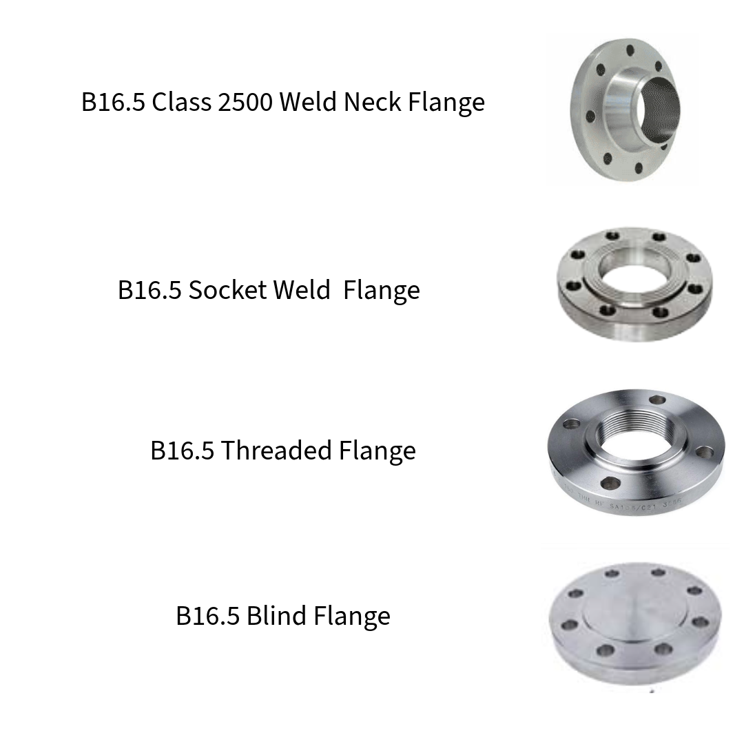
B16.5 is a remarkably comprehensive document. In addition to the plain pipe flange, it covers the full family of flange types in common industrial use:
Weld neck
Socket weld
Threaded
Blind
Slip-on
Lap joint (stub end companion)
Reducing (slip-on and threaded)
It also covers flanged fittings — elbows, tees, crosses, and reducers — in Classes 150 and 300 through NPS 24, with dimensional acknowledgment of higher classes in an appendix.
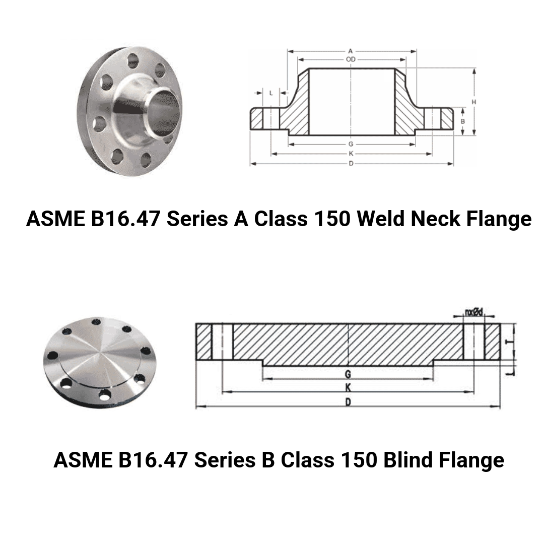
B16.47 covers only two flange types:
Weld Neck
Blind
At the large diameters in scope, slip-on, socket weld, and threaded flanges are impractical and uncommon in service, so the standard simply doesn’t address them. There are also no flanged fittings in B16.47.
Materials: Nickel Alloys Are Excluded from B16.47
Both standards use the same material group numbering system (Group 1.x for carbon and low-alloy steels, Group 2.x for higher-alloy and duplex grades, Group 3.x for austenitic stainless steels), and the pressure–temperature rating tables are structured the same way. However, B16.47 explicitly excludes nickel base alloys, which are included in B16.5. The rationale noted in the standard’s foreword is that these materials were outside the intended scope of the large-diameter standard at the time of its development.
If your process demands an Alloy 625 or similar nickel-base flange at large diameter, B16.47 won’t cover it, and you’ll be working from engineering calculations and applicable code rather than a standard dimensional table.
Ring Joint Gaskets at the Largest Sizes
One additional detail worth noting for inspection and sealing work: B16.47 explicitly states that ring-joint gaskets are not contemplated for NPS 38 and larger flanges. Raised face and flat face configurations remain available across the full size range, but ring joint grooves are not defined at the upper end of the standard. At those diameters, sealing system selection becomes a more application-specific engineering decision.
Quick Reference Summary
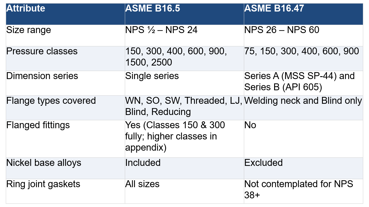
Putting It Together
For the vast majority of process plant piping — refineries, chemical plants, power generation, and general industrial — B16.5 is the workhorse standard. Its size range covers nearly all instrument connections, heat exchanger nozzles, valve bodies, and process piping runs that aren’t classified as large-bore headers or transmission lines.
B16.47 exists to serve the industries where large-bore piping is the norm: long-distance pipelines, compressor stations, storage facilities, large offshore headers, and similar infrastructure. At those diameters, the engineering challenges around fabrication, transportation, and bolted joint assembly are different enough that a dedicated standard makes sense — along with, as the Series A/B distinction shows, enough dimensional history that two traditions had to be reconciled rather than one chosen.
Knowing which standard governs a given flange isn’t just a clerical detail. It determines what dimensional data to reference, what pressure–temperature ratings apply, what bolting is required, and whether the flange in your hand will physically mate with the one on the equipment. Getting that identification right is the starting point for everything else.
The information in this article is provided for general reference purposes only. Always consult and apply the currently approved, project-specific edition of the relevant design code or standard. Codes and standards are revised over time, and the requirements applicable to your project may differ from what is described here. While every effort has been made to ensure accuracy, errors and omissions may exist. FlangeVision and its contributors accept no liability for any decisions made, or actions taken, in reliance on the content of this article.