
ASME B16.20 Gasket Sizes — Quick Reference Chart
If you inspect flanged joints, one of the most common questions in the field is simple: what are the gasket dimensions for this flange? For spiral-wound gaskets — the workhorse gasket for raised-face flanges in process piping — the answer comes from ASME B16.20, Metallic Gaskets for Pipe Flanges. We figured we would make a quick reference chart, scrubbing out all the unnecessary information to help you find the dimensions you require quickly.
The charts below summarize the inside and outside diameters of the gasket sealing element (the spiral windings) for gaskets used with ASME B16.5 flanges (NPS ½ through 24) and ASME B16.47 Series A and Series B flanges (NPS 26 through 60), by pressure class. Note these are the dimensions of the sealing element that seats on the raised face — not the centering ring OD you see at the bolt circle, nor the inner ring ID at the bore. Both rings extend beyond the values in this chart, so measure to the windings, not the ring edges.
Because we are in the business of inspecting flanges, we know this information is useful when following the inspection requirements laid out in ASME PCC-1, Nonmandatory Appendix D (Guidelines for Allowable Gasket Seating Surface Flatness and Defect Depth). This appendix is the go-to reference when assessing whether a flange face is fit for service. The key phrase is gasket seating surface: flatness and surface defects are evaluated across the band where the gasket sealing element actually sits — not across the entire raised face. A scratch or pit outside the gasket OD, or inboard of the gasket ID, has no bearing on the seal. That is exactly why the ID and OD in this chart matter to an inspector: they define the region you measure, and they let you ignore imperfections that fall outside it.
All dimensions are shown in inches with millimeters in parentheses, taken from Tables SW-2.1-1, SW-2.1-2, and SW-2.1-3 of ASME B16.20-2023. The standard thickness of the metallic sealing element for these sizes is 0.175 in. (4.45 mm), with a tolerance of ±0.005 in. (±0.13 mm). A dash (—) means no gasket is listed for that size and class combination.
Spiral-Wound Gaskets for ASME B16.5 Flanges (NPS ½–24)
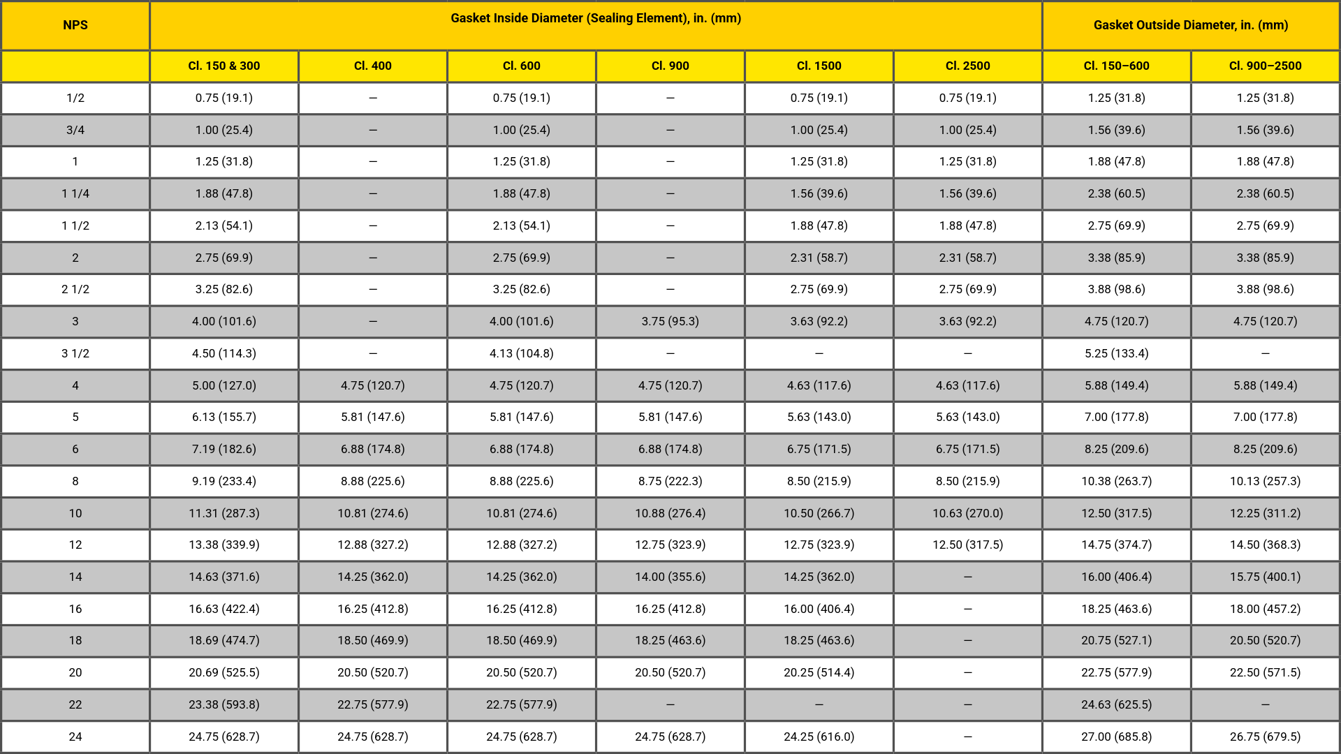
Notes: For Class 400 flanges in NPS ½–3½, use the Class 600 gasket; for Class 900 flanges in NPS ½–2½, use the Class 1500 gasket. There are no NPS 3½ or NPS 22 flanges in Classes 900 and 1500, and no Class 2500 flanges in NPS 3½ or NPS 14 and larger. Gasket OD tolerance: ±0.03 in. (NPS ½–8); +0.06/−0.03 in. (NPS 10–24). Gasket ID tolerance: ±0.016 in. (NPS ½–8); ±0.03 in. (NPS 10–24).
Spiral-Wound Gaskets for ASME B16.47 Series A Flanges (NPS 26–60)

Note: There are no Class 900 flanges in NPS 50 and larger. Gasket ID tolerance: ±0.03 in. (NPS 26–34); ±0.06 in. (NPS 36–60). Gasket OD tolerance: ±0.06 in. Series A flanges were formerly designated MSS SP-44.
Spiral-Wound Gaskets for ASME B16.47 Series B Flanges (NPS 26–60)
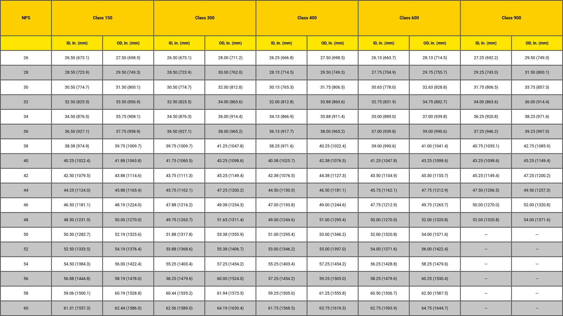
Note: There are no Class 900 flanges in NPS 50 and larger. Gasket ID tolerance: ±0.03 in. (NPS 26–34); ±0.06 in. (NPS 36–60). Gasket OD tolerance: ±0.06 in. Series B flanges were formerly designated API 605 — watch for this on older drawings, because Series A and Series B gaskets of the same NPS and class are not interchangeable.
A Few Field Tips
Always confirm the flange standard before selecting a gasket. NPS 26 and larger flanges can be B16.47 Series A or Series B, and the gasket dimensions differ — sometimes by several inches. When in doubt, measure the bolt circle and compare against the flange standard, or check the line class specification.
If a gasket will not centre on the bolts or the sealing element overhangs the raised face, stop and verify the size and class — a gasket that “almost fits” is usually the wrong gasket. The sealing element should land fully on the raised face with the centering ring resting against the bolts.
This chart is provided as a convenience for quick field reference. It is based on ASME B16.20-2023, with inspection guidance summarized from ASME PCC-1-2022, Nonmandatory Appendix D; always verify dimensions and acceptance criteria against the current editions of the standards and your project specifications before use. Gasket material selection, pressure-temperature ratings, and bolting requirements are separate considerations outside the scope of this chart.